Next: Geometric Description Up: Degenerated Isoparametric Shell Element Previous: Reduced Selective Integration
Figure 2.4: Coordinate Systems for Plane Shell Elements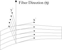 |
The two dimensional shell element is deduced from the three dimensional shell element presented in the previous section. The formulation is reduced by omitting one coordinate out of each of the coordinate systems used, Figure (2.4), and replacing the three dimensional plasticity problem with a plane one. The lamina coordinate system and its transformation matrix  are given in this case as
The fiber direction v2i at node i is given by
 | (50) |
A. Zeiny
2000-09-06