


Next: Computer Implementation and Testing Up: Nonlinear Liquid Sloshing in Previous: On the Right Hand
Invoking the variation of Equation (4.53) gives
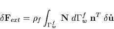 | (180) |
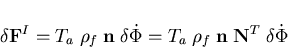
while invoking the variation of equation (4.54) provides
which after linearization gives
 | (183) |
Equation (4.55) simulates the effect of small change in the structure degrees of freedom on the liquid discharge vector, while Equation (4.58) simulates the effect of small change in the liquid degrees of freedom on the pressure force vector applied on the structure. Therefore, the liquid-structure coupling matrix is given as
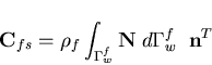 | (184) |
while the structure-liquid coupling matrix is given as
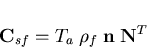 | (185) |
In order to achieve symmetric equations, the liquid-structure coupling matrix should be equal to the transpose of the structure-liquid coupling matrix. For this to be so, to satisfy this condition, one states
 | (186) |
which could be easily maintained by choosing the finite element mesh of both the liquid and the structure domains on the interface to posses the following properties - 1.
- The tributary area served by the structure node coincide with the liquid element edge in contact with the structure, i.e.

- 2.
- The structure node location is chosen such that the shape function vector of the fluid element at the structure node equals to the vector that consists of the ratios of the surface area served by each fluid node to the total surface area in contact with the structure, i.e. the following relation is satisfied
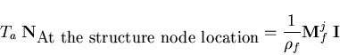 | (187) |
where j is the liquid element edge in contact with the structure node and  is a unit column. For example, in case of linear shape functions, the structure node should be in the middle of the liquid element face, as shown in Figure (4.4).
In case of large amplitude free surface waves, the mesh is updated to follow the liquid boundaries. This makes it impossible to maintain the symmetry conditions. One or more structure nodes may be located along the same liquid element edge and in positions that violate the symmetry conditions. In this case, the closest structure node to the symmetric position is chosen and  is used to couple the liquid element with this structure node only. This technique is found to produce good quadratic convergence. Although using nonsymmetric matrices may be faster to converge, it requires almost double of the symmetric storage and computational cost. The developed approach is found to be convenient and efficient.
The global right hand side is then given as
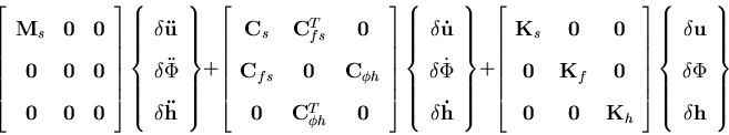 | (188) |
where  and
and  are the matrices resulting from the assembly of either Equation (4.41) or Equation (4.48), and
  is the free surface elevation degrees of freedom vector.
 It should be pointed out that the developed liquid-structure interaction implementation could be also used to handle the nonlinear sloshing problem. The liquid free surface could be treated as a liquid-structure boundary on which the structure has zero stiffness. In order to fulfill the equilibrium condition, the liquid pressure has to be eliminated on this boundary.
Next: Computer Implementation and Testing Up: Nonlinear Liquid Sloshing in Previous: On the Right Hand A. Zeiny
2000-09-06 ![$\displaystyle T_a \; {\bf n} \; \delta \left( P_o-\gamma_f\left[\frac{1}{g} \fr...
...down$ }} \phi.
\mbox{{\boldmath$\bigtriangledown$ }} \phi}{2g}+y\right] \right)$](img462.gif)