

Next: Nonlinear Liquid Sloshing in Up: Nonlinear Liquid Sloshing in Previous: Discrete Finite Element Implementation
Continuous finite element implementation is achieved by working directly from the variational indicator. In order to derive the virtual work statements to be discretized, the variations of Equation (4.10) with respect to  and un are taken, thus
Equation (4.42) may be rewritten as
 | (169) |
Since the virtual variables are arbitrary, the Euler equations that govern the liquid behavior are
Equation (4.46) represents the kinematic condition at the liquid-structure interface  and at the free surface
  . On the other hand, Equation (4.47) represents the dynamic condition only at the free surface
  because un is considered as unknown only at the free surface.
 Linearization of Equations (4.42) and (4.43) is achieved by assuming that the free surface elevation h is equal to the normal displacement of the free surface un and ignoring the term 
 in Equation (4.12), this yields to
where j is the free surface edge number,  is the liquid velocity vector and
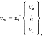
  is the normal velocity vector at free surface nodes. The normal velocity at a free surface node i is computed as
 | (176) |
where  is the normal vector to the free surface at the node, and Vx and Vz are the velocity of free surface node i in the x and z directions due to the mesh speed, respectively.


Next: Nonlinear Liquid Sloshing in Up: Nonlinear Liquid Sloshing in Previous: Discrete Finite Element Implementation A. Zeiny
2000-09-06 ![]() and un are taken, thus
and un are taken, thus 
![]()
![]() in Equation (4.12), this yields to
in Equation (4.12), this yields to 