


Next: On the Left Hand Up: Nonlinear Liquid Sloshing in Previous: Nonlinear Liquid Sloshing in
As shown in Figure (4.4), a tank node in contact with the liquid domain is subjected to the liquid pressure and, at the same time, delivers energy to the liquid. Since the liquid mesh is updated after each iteration to comply with the new free surface shape and deformed boundaries of the structure, the liquid nodes are moving with respect to the structure nodes. A geometric analysis, similar to what need to be performed in contact analysis, is applied on liquid and structure nodal coordinates and displacements to determine which liquid element is in contact with the current structure node. The normal velocity compatibility condition at liquid-structure interfaces gives
 | (177) |
This condition causes an external discharge vector to be applied on the liquid element due to the normal velocity of the structure boundary. Hence,
 | (178) |
where  is the liquid element surface in contact with the tank wall and
  is the shape function vector for the element nodes located on that surface.
Figure 4.4: Boundary Conditions at a Structure Node in Contact with a Liquid Element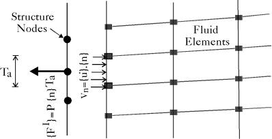 |
The dynamic condition at liquid-structure interfaces requires that the liquid pressure be integrated and applied on the structure node, which gives
 | (179) |
where Ta is the tributary area served by the structure node and P is the total pressure at the structure node given by Equation (4.12).
Next: On the Left Hand Up: Nonlinear Liquid Sloshing in Previous: Nonlinear Liquid Sloshing in A. Zeiny
2000-09-06