


Next: Effect of Foundation Stiffness Up: Nonlinear Earthquake Response of Previous: Anchored Tank Response
In order to evaluate the effect of the base boundary conditions on the response of liquid storage tanks, the tank base plate was considered supported on a tensionless elastic foundation of a uniform stiffness of 1000 lb/in/in2 in compression. Table (5.5) provides the unanchored tank response using the small deflection theory.
Table 5.5: Unanchored Tank Response - Small Deflection Assumptions| Response Parameter | El Centro Record | Northridge Record | | | Broad | Tall | Broad | Tall | | Top Lateral Acceleration | 1.999 g | 0.934 g | 2.001 g | 0.845 g | | Top Lateral Deflection (in) | 7.43 | 5.66 | 6.24 | 13.49 | | Total OTM / WR | 0.200 | 0.380 | 0.198 | 0.477 | | Wall OTM / WR | 0.075 | 0.317 | 0.065 | 0.353 | | Base Shear / W | 0.292 | 0.243 | 0.258 | 0.293 | | Base Axial Stress (Ksi) | -4.75 | -6.71 | -4.62 | -7.90 | | Base Hoop Stress (Ksi) | 9.56 | 8.46 | 10.84 | 8.07 | | Axial Stress at 0.25H (Ksi) | -2.47 | -4.69 | -2.04 | -5.58 | | Hoop Stress at 0.25H (Ksi) | 19.85 | 11.51 | 21.50 | 12.89 | | Maximum Uplift Displacement (in) | 1.05 | 1.75 | 1.50 | 2.87 | | Minimum Contact Area | 0.732 | 0.671 | 0.733 | 0.610 |
|
Figures (5.9), (5.10), (5.11) and (5.12) display time history comparisons between the anchored and the unanchored broad tank for the overturning moment measured at the center of the base plate and for the base axial stresses when subjected to Northridge and El Centro ground motions, respectively. Figures (5.13), (5.14), (5.15) and (5.16) show the same comparison for the tall tank. The response of the unanchored tank was governed primarily by a rocking motion. This mode was found to have a dominant ``period'' of 0.41 sec for the broad tank and 0.82 sec for the tall tank. Based on these periods, the foundation rocking damping is estimated to be  . On the other hand, the response of the anchored tank was governed primarily by the flexible-impulsive pressure component which has a fundamental period of 0.162 sec for the broad tank and 0.189 sec for the tall tank. Since the rocking period is relatively large as compared to the flexible-impulsive period, the overturning moment exerted on the anchored tank may be larger than that exerted on the unanchored tank. However, due to the nature of the boundary conditions associated with the base of the unanchored tank, the axial and hoop stresses at the bottom of the unanchored tank shell were larger than those of the anchored tank. The response of unanchored tanks was dominated by the uplift mechanism which varied nonlinearly with the intensity and frequency of input motions. The coupling of uplift mechanism with out-of-round distortions resulted in high compressive axial membrane stresses developed over a narrow contact zone. This effect is reflected by the sharp peaks on the compression side of the time history diagrams of the axial stress that occurred simultaneously with large uplifting displacements. The cases on which the axial stress at the bottom of the anchored tank shell were larger than those of the unanchored tank are attributed to the large difference between the overturning moments in the two tanks. Yet, sharp peaks are still shown on the compression side of the axial stress time history diagrams of these tanks.
Figure 5.9: Overturning Moment at Center of Base of the Broad Tank, Northridge Record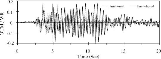 |
Figure 5.10: Base Axial Stress in the Broad Tank Shell, Northridge Record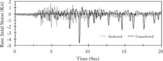 |
Figure 5.11: Overturning Moment at Center of Base of the Broad Tank, El Centro Record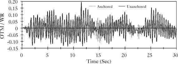 |
Figure 5.12: Base Axial Stress in the Broad Tank Shell, El Centro Record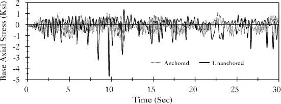 |
Figure 5.13: Overturning Moment at Center of Base of the Tall Tank, Northridge Record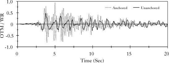 |
Figure 5.14: Base Axial Stress in the Tall Tank Shell, Northridge Record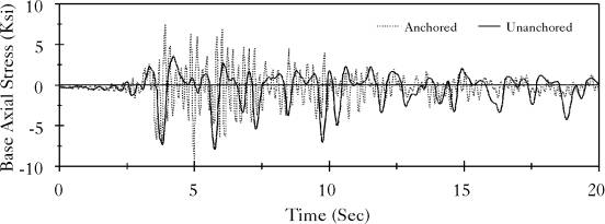 |
Figure 5.15: Overturning Moment at Center of Base of the Tall Tank, El Centro Record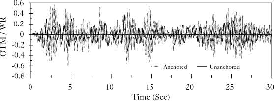 |
Figure 5.16: Base Axial Stress in the Tall Tank Shell, El Centro Record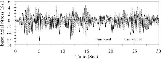 |
The contact characteristics of the unanchored tank with its foundation are important factors in evaluating the response of such a tank. Figures (5.17), (5.19), (5.21) and (5.23) show the uplift displacement of the two extreme opposite points on the principal diameter which parallels the earthquake excitation of the broad and tall tanks, respectively, when subjected to the Northridge and El Centro ground motions. They show that the uplift displacement on the tension side is much higher than the penetration displacement on the compression side. Such a behavior is expected due to the tensionless nature of the foundation. In addition, Figures (5.18), (5.20), (5.22) and (5.24) show the time history of the change in the area of contact of the base plate with the foundation (Ac) as compared to the total area (At).
Figure 5.17: Uplift Displacement of the Two Corner Points on the Principal Diameter of the Broad Tank, Northridge Record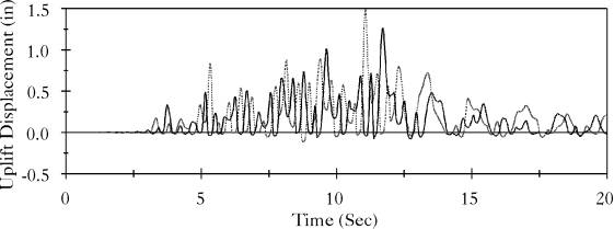 |
Figure 5.18: Percentage of Bottom Plate Area of Broad Tank in Contact with the Foundation, Northridge Record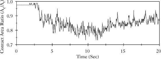 |
Figure 5.19: Uplift Displacement of the Two Corner Points on the Principal Diameter of the Broad Tank, El Centro Record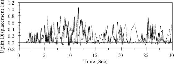 |
Figure 5.20: Percentage of Bottom Plate Area of Broad Tank in Contact with the Foundation, El Centro Record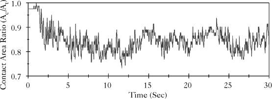 |
Figure 5.21: Uplift Displacement of the Two Corner Points on the Principal Diameter of the Tall Tank, Northridge Record |
Figure 5.22: Percentage of Bottom Plate Area of Tall Tank in Contact with the Foundation, Northridge Record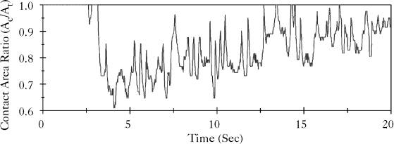 |
Figure 5.23: Uplift Displacement of the Two Corner Points on the Principal Diameter of the Tall Tank, El Centro Record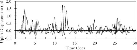 |
Figure 5.24: Percentage of Bottom Plate Area of Tall Tank in Contact with the Foundation, El Centro Record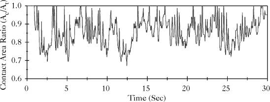 |
Next: Effect of Foundation Stiffness Up: Nonlinear Earthquake Response of Previous: Anchored Tank Response A. Zeiny
2000-09-06