


Next: Condition of Sliding Contact Up: Finite Element Formulation Previous: Finite Element Formulation
A contactor node c is assumed to be in sticking contact during iteration i under one of two conditions:
- 1.
- The contactor node has penetrated into the target body in iteration (i-1) whereas it was not in contact after iteration (i-2).
- 2.
- The friction resistance during contact is sufficient to prevent sliding.
In the first case, the penetration vector  on the right hand side of Equation (3.6) is set such that
  for the next iteration eliminates the current penetration of the contactor node into the target surface. Such constraints on the displacement vector generate the contact forces. These contact forces is further checked against the law of friction to determine whether state of sticking contact will remain or slippage will take place.
 The constraints to be enforced in the case of sticking contact are
These constraints are enforced through the matrix  , and the vectors
  and . The vector is required to recover the residual from the contact forces resulting from the applied constraints. This residual has been previously computed from the equilibrium of the entire system. Although the contact forces could be directly computed from the values of
  , but the equilibrium approach gives better accuracy.
 Figure (3.4) shows a contactor node c that is in contact with the target element connected to the three nodes i, j and k. A geometric analysis of the nodal coordinates and deformations is performed to determine the target element associated with each contactor node, the target's attached nodes, coordinates of point c' and the nondimensional triangular coordinates L1, L2 and L3. If node c penetrates inside the target element, then the penetration vector required to correct this error is given by
 | (111) |
where  and
and  are the position vector of points c' and c in the current iteration, respectively. Sticking point c' to the target element requires that
 | (112) |
Eliminating the penetration vector gives the constraint matrix as
![\begin{displaymath}[ K_\lambda^T]= C_\lambda
\left[ \begin{array}{cccccccccccc} ...
...0&L_3&0\\
0&0&-1&0&0&L_1&0&0&L_2&0&0&L_3\
\end{array} \right]
\end{displaymath}](img302.gif) | (113) |
where  is a scale factor used to scale the constraint matrix and the penetration vector to avoid ill-conditioned coefficient matrix in the left hand side. The matrix equation given as
![\begin{displaymath}[K_\lambda^T]
\left\{ \begin{array}{c}
{\bf u}_{c} \\
{\b...
...{\bf u}_{j} \\
{\bf u}_{k}
\end{array} \right\}
=
\{ P \}
\end{displaymath}](img304.gif) | (114) |
is then assembled to the global system to enforce the sticking contact Condition.
Figure 3.4: Geometry of Sticking Contact Condition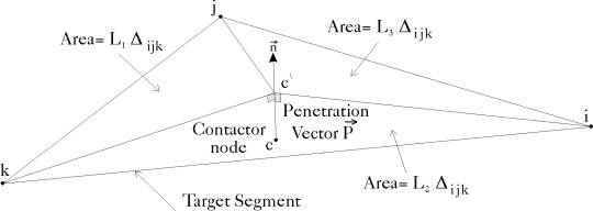 |
Next: Condition of Sliding Contact Up: Finite Element Formulation Previous: Finite Element Formulation A. Zeiny
2000-09-06