![]()
![]()
![]()
![]()
Next: Impact of Proposed Work Up: Proposed Finite Element Modeling Previous: Examples of Proposed Time
Examples of Proposed Static Push Runs
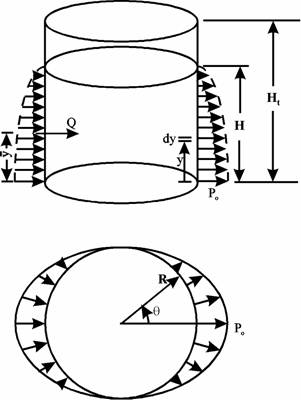
Figure 12: Pseudo-Dynamic Loads Applied on Tank Wall |
|
The lateral static push analysis is performed to investigate the behavior of unanchored liquid storage tanks when subjected to lateral earthquake loads. As the tank is pushed in the lateral direction, it uplifts from its foundation and develops a similar uplifting mechanism to that occurred under earthquake excitations. Results of the static push test will help to establish relationships between applied overturning moment and axial stresses as well as allowable buckling stresses. As shown in Figure (12), a hydrodynamic pressure distribution was assumed on the tank wall as
| (16) |
where y is the elevation of a point on the shell measured from the base, H is the fluid depth, ![]() is the angle measured from the axis of excitation and po is the pressure amplitude at the tank base at
is the angle measured from the axis of excitation and po is the pressure amplitude at the tank base at ![]() . If M denotes the overturning moment about the center of the base, then
. If M denotes the overturning moment about the center of the base, then
M | = |
| (17) |
| = |
|
|
| = |
|
|
and similarly, if Q is the base shear, then
Q | = |
| (18) |
| = |
|
|
| = |
|
|
and accordingly
| (19) |
Figures (13) and (14) show the finite element mesh used to model the broad and the tall tanks, respectively. The broad tank showed buckling at a value of OTM/WR=0.077 which indicates that the broad tank may have buckled during transient responses presented before. On the contrary, the tall tank did not experience buckling until it overturns. Figures (15) and (16) show the variation of uplift displacement and axial stress at shell bottom with the applied seismic overturning moment.
![]()
![]()
![]()
![]()
Next: Impact of Proposed Work Up: Proposed Finite Element Modeling Previous: Examples of Proposed Time
2000-05-12