![]()
![]()
![]()
![]()
Next: Examples of Proposed Static Up: Proposed Finite Element Modeling Previous: Proposed Finite Element Modeling
Examples of Proposed Time History Runs
Two examples of two extreme cases are presented. Figures (2) and (3) show the finite element mesh used for the broad and tall tanks, respectively. The tank wall, roof and base plate are modeled using degenerated nonlinear shell elements. The liquid domain is modeled using Eulerian liquid elements.
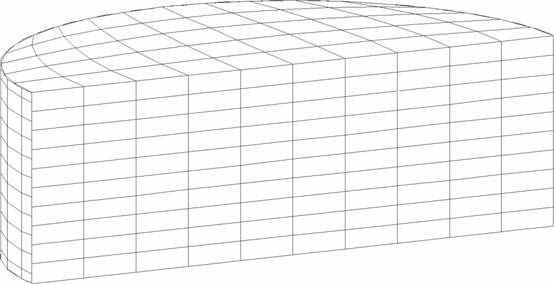
Figure 2: Finite Element Mesh of the Coupled Liquid-Broad Tank System |
|
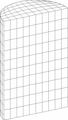
Figure 3: Finite Element Mesh of the Coupled Liquid-Tall Tank System |
|
The broad tank is 40 ft high and has a radius of 60 ft. The shell thickness is assumed constant of 1 inch and the base plate is considered having 1 inch of uniform thickness. The tall tank is 72 ft of high, 24 ft in radius, and has both shell and base thickness of 1 inch. Both tanks are assumed full of water to capacity. Each of the two tanks were subjected to two different earthquake motions: the East-West component of the 1940 El Centro earthquake, which has a peak ground acceleration of 0.214 g, and the record from the Northridge earthquake measured at the Arleta site, which has a peak ground acceleration of 0.344 g, and measured in a direction of 90![]() from the hypocenter direction. Figures (4), (5), (6) and (7) display time history comparisons between the anchored and the unanchored broad tank for the overturning moment measured at the center of the base plate and for the base axial stresses when subjected to Northridge and El Centro ground motions, respectively. Figures (8), (9), (10) and (11) show the same comparison for the tall tank. The response of the unanchored tank was governed primarily by a rocking motion. This mode was found to have a dominant ``period'' of 0.41 sec for the broad tank and 0.82 sec for the tall tank. Based on these periods, the foundation rocking damping is estimated to be
from the hypocenter direction. Figures (4), (5), (6) and (7) display time history comparisons between the anchored and the unanchored broad tank for the overturning moment measured at the center of the base plate and for the base axial stresses when subjected to Northridge and El Centro ground motions, respectively. Figures (8), (9), (10) and (11) show the same comparison for the tall tank. The response of the unanchored tank was governed primarily by a rocking motion. This mode was found to have a dominant ``period'' of 0.41 sec for the broad tank and 0.82 sec for the tall tank. Based on these periods, the foundation rocking damping is estimated to be ![]() . On the other hand, the response of the anchored tank was governed primarily by the flexible-impulsive pressure component which has a fundamental period of 0.162 sec for the broad tank and 0.189 sec for the tall tank. Since the rocking period is relatively large as compared to the flexible-impulsive period, the overturning moment exerted on the anchored tank may be larger than that exerted on the unanchored tank. However, due to the nature of the boundary conditions associated with the base of the unanchored tank, the axial and hoop stresses at the bottom of the unanchored tank shell were larger than those of the anchored tank. The response of unanchored tanks was dominated by the uplift mechanism which varied nonlinearly with the intensity and frequency of input motions. The coupling of uplift mechanism with out-of-round distortions resulted in high compressive axial membrane stresses developed over a narrow contact zone. This effect is reflected by the sharp peaks on the compression side of the time history diagrams of the axial stress that occurred simultaneously with large uplifting displacements. The cases on which the axial stress at the bottom of the anchored tank shell were larger than those of the unanchored tank are attributed to the large difference between the overturning moments in the two tanks. Yet, sharp peaks are still shown on the compression side of the axial stress time history diagrams of these tanks.
. On the other hand, the response of the anchored tank was governed primarily by the flexible-impulsive pressure component which has a fundamental period of 0.162 sec for the broad tank and 0.189 sec for the tall tank. Since the rocking period is relatively large as compared to the flexible-impulsive period, the overturning moment exerted on the anchored tank may be larger than that exerted on the unanchored tank. However, due to the nature of the boundary conditions associated with the base of the unanchored tank, the axial and hoop stresses at the bottom of the unanchored tank shell were larger than those of the anchored tank. The response of unanchored tanks was dominated by the uplift mechanism which varied nonlinearly with the intensity and frequency of input motions. The coupling of uplift mechanism with out-of-round distortions resulted in high compressive axial membrane stresses developed over a narrow contact zone. This effect is reflected by the sharp peaks on the compression side of the time history diagrams of the axial stress that occurred simultaneously with large uplifting displacements. The cases on which the axial stress at the bottom of the anchored tank shell were larger than those of the unanchored tank are attributed to the large difference between the overturning moments in the two tanks. Yet, sharp peaks are still shown on the compression side of the axial stress time history diagrams of these tanks.
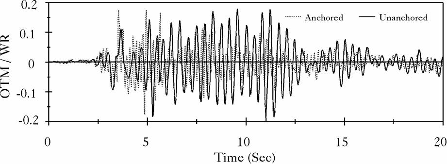
Figure 4: Overturning Moment at Center of Base of the Broad Tank, Northridge Record |
|
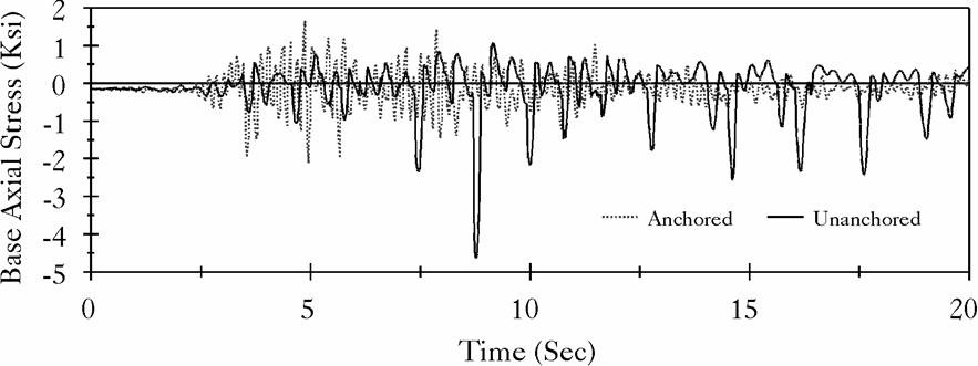
Figure 5: Base Axial Stress in the Broad Tank Shell, Northridge Record |
|
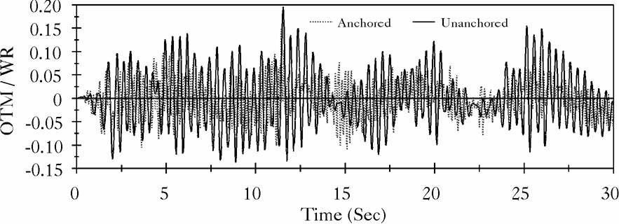
Figure 6: Overturning Moment at Center of Base of the Broad Tank, El Centro Record |
|
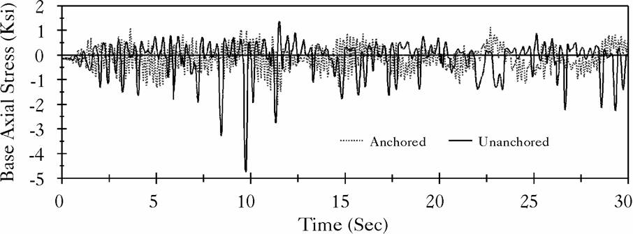
Figure 7: Base Axial Stress in the Broad Tank Shell, El Centro Record |
|
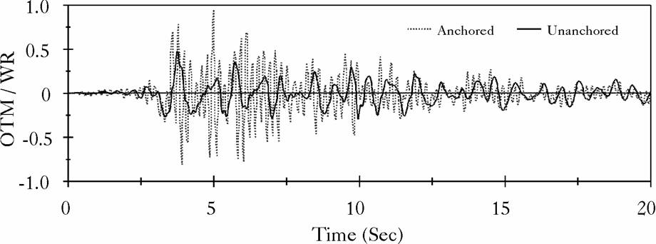
Figure 8: Overturning Moment at Center of Base of the Tall Tank, Northridge Record |
|
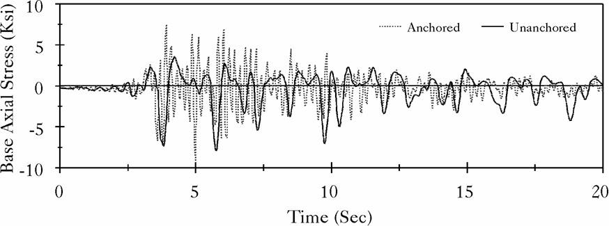
Figure 9: Base Axial Stress in the Tall Tank Shell, Northridge Record |
|

Figure 10: Overturning Moment at Center of Base of the Tall Tank, El Centro Record |
|
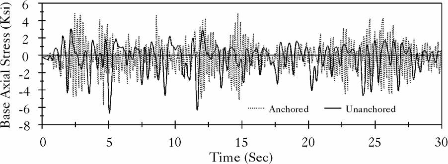
Figure 11: Base Axial Stress in the Tall Tank Shell, El Centro Record |
|
![]()
![]()
![]()
![]()
Next: Examples of Proposed Static Up: Proposed Finite Element Modeling Previous: Proposed Finite Element Modeling
2000-05-12